“3D-Import” module: Automatically detect and programme profile machining
The “3D import” module provides users with “a miracle at the press of a button”. The development was difficult and lengthy – the result is a quantum leap in profile processing.
Behind the 3D import there is a 3D converter that automatically detects processes in 3D modules (.sat/.step/.x_t) and programs them in seconds. Time-consuming, error-prone data entry by hand during the programming of processes like drill holes, circular pockets, grooves, slots, rectangular features, notches, saw cuts and free-forms can often be eliminated.
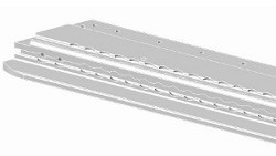 3D model of a 2,400 mm long profile on which 261 presentations are programmed. 3D models stored as step files, sat files, or Parasolid files can automatically be programmed with the 3D converter. |
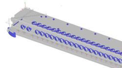 Result after using the 3D converter: The converter has detected the cross-section of the profile as well as all the processes that are then programmed automatically. All that took only a few seconds. |
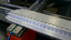 The ncw file provided by the 3D converter can now be used to control the profile processing centre. Programming can be done in seconds to enable cost-effective work. |
In practice, work with the 3D converter looks like the following: Call up the 3D module, use the 3D converter – and you’re done. The program can now be sent to the target machine. The programming effort is often less than a second – the rod processing centre hasn’t even finished starting up and the processing program is already available. All processes are then available in the eluCad programming software and can be edited further.
Enormous time savings
The following idea leads to the development of the converter: New parts are often designed using a piece of software (e.g. Inventor, Pro/Engineer, Solidworks) that creates three-dimensional models. Once the design is complete, a 3D model is available that already contains all the information needed for later profile machining. How long is the profile, what is its cross-section, what machining steps must be carried out? The newly developed software starts with the question: How can this information be transformed into a file that can then be the basis for the movements of a profile machining centre? The answer is the 3D converter. It generates the profile as a DXF file. In combination with the profile length, this results in a three-dimensional view. The “bounding box” based on the maximum dimensions is calculated in parallel with this. This information is important for maintaining a safe distance. All machining information is output as an NCW file, which can then be used for the programming of profile machines.
The 3-D converter is an application for the area “automated feature recognition“ (AFR). With “feature completion”, machining steps are completed that are only partly specified, e.g. because they are on the edge.
Numerous advantages
The use of the 3D converter provides a series of advantages.
- In terms of speed, the 3D detector represents a quantum leap forwards in comparison with manual programming. 100 machining steps can be programmed in 5 seconds, for example – because this process is automated.
- Working with the 3D detector is not as error-prone as manual programming. When inputting data by hand, digits are easy to transpose, for example. The automated software, on the other hand, works precisely and without tiring.
- The automatic input of machining steps is more precise. The 3D detector calculates in the dimensions used in the 3D model. A programmer interprets any data during input: Is this dimension from the front edge or from the back edge? Does the dimension end in the middle of the drill hole or on its edge?
- The 3D converter increases productivity with minimum manual intervention.
- The 3D converter enables the reuse of 3D data in the production process, increasing process automation
- The automatically detected machining steps can be further processed.
- The application relieves the burden of the programming department and reduces programming costs.
- NC programs are produced in a very short time: Thus the deadlock in the process cycle from design to machine can be overcome.
- In manual programming, there may be lapses of concentration, oversights, typos, or errors of interpretation – automatic programming with 3D import eliminates all these sources of human error.
Individual adaptations
The 3D converter permits the reuse of 3D data, for example data available as a step file, SAT file, or parasolid file. In volume models, holes, circular pockets, grooves, countersinks, slots, rectangles, notches, saw cuts and free forms are detected and programmed by the converter. All automatically programmed machining steps are clearly recognisable to the user in the screen view. By a centre visible in the machining step and by the use of a different colour.
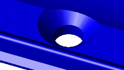 The 3D converter detects holes and recesses – even when they’re incomplete and lie on slanted surfaces. |
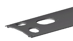 The 3D converter detects: Circular pockets, holes, elongated holes, with 4th axis. |
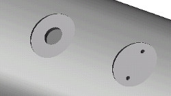 Circular pockets for the spot-facing of surfaces are assigned the attribute for countersinking the pocket. |
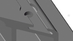 Both circular segments are recognised as related, since both have the same centre and are accessible from the same direction. |
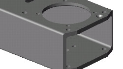 The following can be detected: Holes on multiple sides and standard processes. The chamfers are generated on the profile ends by saw cuts. |
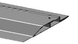 The following can be detected: Saw cuts on the profile end, also with two angles. |
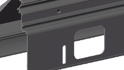 Recessed holes have a depth table that permits technologically perfect approach positions. |
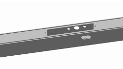 Automatically programmed: Multi-sided processes, such as those used in door manufacturing. |
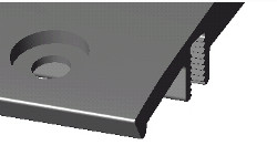 The following can be detected: Holes with flat countersink at arbitrary angles. |
The 3D converter also detects slanted holes, but is not built for bent parts. It is also not suitable to recognise machining processes that are a combination of several machining steps. Custom machining steps not programmed by the 3D converter are immediately visible to the user in the screen view as unrecognised machining steps.
The 3D converter recognises most standard machining steps, and the automatic programming software is under continual development based on experience and is ever more powerful. Even if all machining steps cannot be recognised 100% in every case, the 3D converter is a great help in practice.
Test the 3D converter for free
Innovation is at its most advanced when it allows you to automate work that is tiresome, error-prone and time-consuming. This is the sense in which the 3D converter is advanced. In a software product like the 3D converter, a lot goes on in the background. In its effects, the software is as effective as an Internet search engine, for example: The user of the PC may not see much, but the end effect provides specific information within seconds. For example, a facade designer who wants to create a tilted facade in which the surface meet at different angles can program very quickly with the 3D converter. The angles required for the roof slant don’t even need to be calculated by the programmer, because the 3D converter reads this type of information out of the volume model.
People interested in testing the 3D converter out can contact elusoft. The test is free of charge. Please take note: The 3D converter only works together with eluCad. Interested people that don’t yet have eluCad can receive a demo from elusoft over the Internet, or can ask for a personal presentation.
